
Product Categories:Data Center Solution
Intelligent Technology
iTAC120M Series Phase-adjustable Power distribution Module
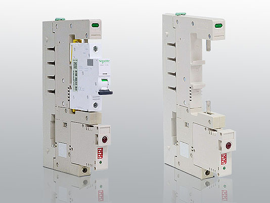


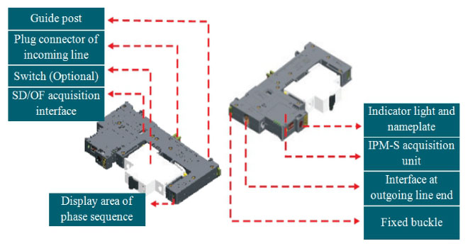

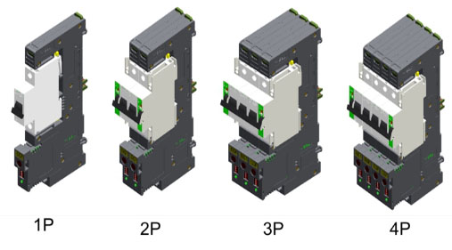
|
Model |
iTAC120M series |
||
|
Number of poles |
1, 2, 3 and 4 poles |
||
|
Rated current |
(1-63A) depending on the rated current of selected miniature circuit breaker |
||
|
Rated voltage |
AC |
Single pole |
230/400V |
|
Multi-pole |
400V |
||
|
DC |
Single pole |
110/220V |
|
|
Temperature range |
Normal working environment |
Temperature:-5~+40℃; humidity: 0~90%, without condensation |
|
|
Storage environment |
Temperature:-40~+70℃; humidity: 0~90%, without condensation |
||
|
Output wiring range |
0.75~25mm2 |
||
|
Tightening torque |
3.5 Nm |
||
|
Communication mode |
RS 485 |
||
|
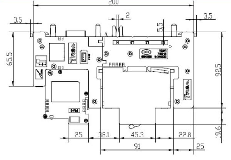
Dimension of single-P assembly Width * depth * height |
200*130*18 mm |
||
|
Parameter name |
Symbol |
Unit |
Precision |
Measurement Range |
iTAC 120M |
iTAC 121M |
iTAC 122M |
|
Single-phase voltage |
U |
V |
0.2% |
0~400 |
- |
■ |
■ |
|
Single-phase current |
I |
A |
0.5% |
0~63 |
- |
■ |
■ |
|
Frequency |
Hz |
Hz |
0.01Hz |
45~65 |
- |
■ |
■ |
|
Active power |
P |
KW |
0.5% |
|
- |
■ |
■ |
|
Reactive power |
Q |
KVAR |
0.5% |
|
- |
■ |
■ |
|
Apparent power |
S |
KAV |
0.5% |
|
- |
■ |
■ |
|
Power factor |
PF |
|
0.5% |
|
- |
■ |
■ |
|
Active electrical degree |
KWh |
KW.h |
0.5% |
|
- |
■ |
■ |
|
Voltage harmonic wave (THD%) |
Uh |
|
0.5% |
|
- |
- |
■ |
|
Current harmonic wave (THD%) |
Ih |
|
0.5% |
|
- |
- |
■ |
|
Temperature |
T |
℃ |
0.5% |
-10~100 |
■ |
■ |
■ |
|
Open/closed state(switch) |
DI |
|
|
|
■ |
■ |
■ |
|
Switch failure state |
DI |
|
|
|
■ |
■ |
■ |
|
Over-current alarm |
I |
A |
|
|
- |
■ |
■ |
|
High & low temperature alarms |
T |
℃ |
|
|
■ |
■ |
■ |
|
Communication |
|
RS485, baud rate: 4,800, 9,600, 19,200, 38,400, 57,600, 115,200 |
|||||
|
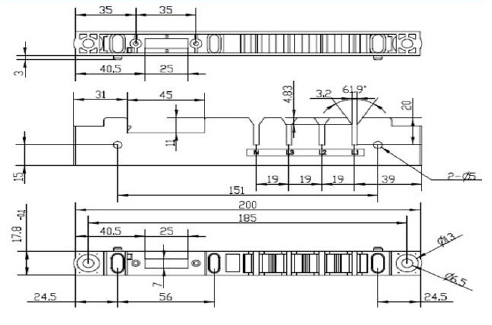
iTAC120M series phase-selector assembly |
|||
|
Product name |
Packing specification |
Product code |
|
|
iTAC120M (Monitor switching and the temperature) |
One pluggable phase selector base,
one cascade base, and one IPM- S1 collection module
|
iTAC120M |

Phase selector assembly
(without the switch)
|
|
iTAC121M (Monitor power quality without harmonic ) |
One pluggable phase selector base,
one cascade base, and one IPM-S3 collection module
|
iTAC121M |
|
|
iTAC122M (Monitor power quality and harmonic) |
One pluggable phase selector base,
one cascade base, and one IPM-S collection module
|
iTAC122M |
|
|
Note: If multi-pole switches are needed, please communicate with pre-sale technical personnel beforehand. |
|||
|
Pluggable phase-selector base |
The assembly without the collection module
|
|||
|
Specification |
Number of packages |
Product code |
||
|
iTAC120M pluggable phase-selector base, 63A |
1 |
iTAC120M-B |
||
|
iTAC121M pluggable phase-selector base, 63A |
1 |
iTAC121M-B |
||
|
iTAC122M pluggable phase-selector base, 63A |
1 |
iTAC122M-B |
||
|
Note: If you need multi-pole switch combination, please communicate with pre-sale technical personnel beforehand.
|
||||
|
Collection module |
Data acquisition module |
|||
|
Specification |
Number of packages |
Product code |
||
|
Data acquisition module of iTAC122M assembly |
1 |
IPM-S |
||
|
Data acquisition module of iTAC121M assembly |
1 |
IPM-S3 |
||
|
Data acquisition module of iTAC120M assembly |
1 |
IPM-S1 |
||
|
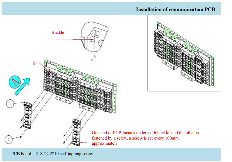
Communication adapter plate |
Communication adapter plate
|
|||
|
Specification |
Number of packages |
Product code |
||
|
Communication adapter plate -02,
44*270.8mm, installed with 13 molded assemblies
|
1 |
iTAC-PCB13 |
||
|
Communication adapter plate -01, 44*470.8mm,
installed with 24 molded assemblies
|
1 |
iTAC-PCB24 |
||
|
Communication adapter plate -03, 44*516.0mm,
installed with 27 molded assemblies
|
1 |
iTAC-PCB27 |
||
|
Note: Ф4.2*10 self-tapping screws shall be provided by yourself at installation. |
||||
|
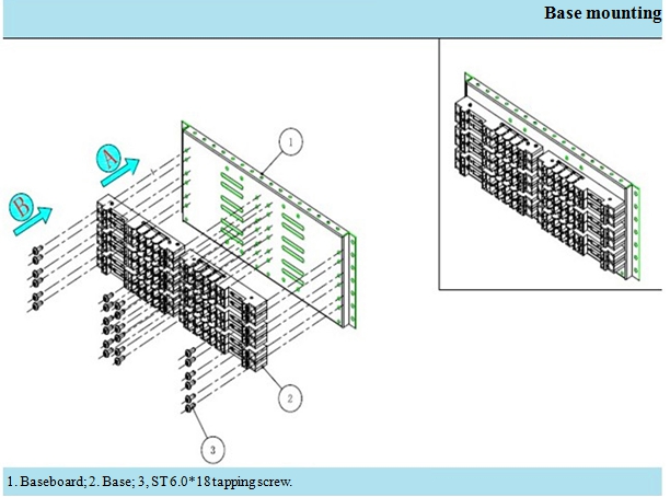
Base plate for installation |
Base plate for installation |
||
|
Specification |
Number of packages |
Product code |
|
|
Base plate for installation-02, 456*274mm, installed with 26 molded assembles |
1 |
iTAC-26P |
|
|
Base plate for installation-01, 456*474mm, installed with 48 molded assembles |
1 |
iTAC-48P |
|
|
Base plate for installation-03, 456*549mm, installed with 54 molded assembles |
1 |
iTAC-54P |
|
|
Note: Ф6.0*18 bolts shall be provided by yourself at installation. |
|||
|
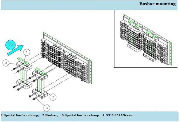
Standard copper bus-bar |
Standard copper bus-bar |
||
|
Specification |
Number of packages |
Product code |
|
|
Standard copper bus-bar, 20*3mm*2m, 200A |
1 |
iTAC-CU |
|
|
Special bus-bar clamp |
Special bus-bar clamp |
||
|
Specification |
Number of packages |
Product code |
|
|
Special bus-bar clamp -01, specially for 20*3mm standard copper bus-bar |
1 |
iTAC-CU01 |
|
|
Special bus-bar clamp -02, specially for 20*3mm standard copper bus-bar |
1 |
iTAC-CU02 |
|
|
Note: Bus-bar clamp -01 and bus-bar clamp-02 shall be used in pair and used as fixed copper bus-bar, and Ф6.0*45 bolts shall be provided by yourself at installation.
|
|||
|
Cascade base |
Cascade base |
||
|
Specification |
Number of packages |
Product code |
|
|
Length * width * height 200*18*30mm |
1 |
iTAC-B |
|
|
Single-P protective cover plate |
Single-P protective cover plate |
||
|
Specification |
Number of packages |
Product code |
|
|
Length * width 200*18mm |
1 |
iTAC-TP |
|
|
Note: It is only for extra protection. It is flexibly demand and used with the common base set together. |
|||


|
Quantity of assemblies
without auxiliary contact
|
Width (mm) |
Depth (mm) |
Height (mm) |
Weight including the switch (kg) |
|
1 |
200 |
150 |
18 |
0.5 |
|
9 |
162 |
4.5 |
||
|
18 |
324 |
9 |
||
|
27 |
486 |
13.5 |
||
|
36 |
666 |
18 |
||
|
45 |
828 |
22.5 |
||
|
54 |
990 |
27 |
||
|
Quantity of assemblies
with auxiliary contact
|
|
|||
|
1 |
200 |
150 |
27 |
0.5 |
|
9 |
243 |
5 |
||
|
18 |
486 |
10 |
||
|
27 |
747 |
15 |
||
|
36 |
990 |
20 |
||

|
Binary system |
10000 |
01000 |
11000 |
00100 |
10100 |
01100 |
11100 |
00010 |
|
Decimal system |
1 |
2 |
3 |
4 |
5 |
6 |
7 |
8 |
|
Binary system |
10010 |
01010 |
11010 |
00110 |
10110 |
01110 |
11110 |
00001 |
|
Decimal system |
9 |
10 |
11 |
12 |
13 |
14 |
15 |
16 |
|
Binary system |
10001 |
010001 |
11001 |
00101 |
10101 |
01101 |
11101 |
00011 |
|
Decimal system |
17 |
18 |
19 |
20 |
21 |
22 |
23 |
24 |
|
Binary system |
10011 |
01011 |
11011 |
00111 |
10111 |
01111 |
|
|
|
Decimal system |
25 |
26 |
27 |
28 |
29 |
30 |
|
|
X. Use and Maintenance
1. The product can’t be exposed to rain during transportation & safekeeping and shall be placed or installed free from the invasion of rain.
2. The product shall be regularly inspected during operating, and the inspection period depends on the work condition, and the power supply shall be cut off during the inspection. The inspection items mainly include:
A. Remove the dust and dirt, and particularly remove the dirt between incoming and outgoing line levels.
B. Tighten the binding screws.
XI. Safety Precautions
1. While installing the products, the operation in live isn’t allowed so as to prevent the electric shock:
2. The live wire ( phase wire) to earth short-circuit or null wire ( neutral wire) and live wire touching method is not employed to test the product performance so as to avoid endangering the personal safety.
3. While installing, the wiring screw should be screwed up tightly, and the lead wire can’t loosen or pulled out easily, the cross section of lead wire should be selected strictly according to the requirement specified in this instruction;
4. It is strictly forbidden to operate the circuit breaker with wet hands, otherwise, the electric shock accident may occur possibly.
XII. Appendixes
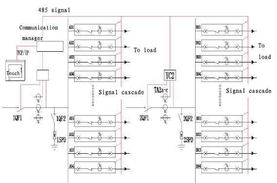
Appendix 1 Typical Array Cabinet System Diagram
Appendix 2 Communication Base Plate Wiring Diagram

Note: V01 and V21 of communication base plate are two groups of independent 5V power supply.

Follow us